


Theory And Design Of Perpetual Motion Machines
1.0 Introduction
1.1Note: The following paper is a technical condensation of the book "To the Stars!" which has been written by Arindam Banerjee for popular scientific appeal. This book has been freely available to the whole world via Internet since September 2000, and may be found at the following web site:
1.2 The book To the Stars! describes the principles for the design of interstellar spacecraft. They would employ the theory and design of perpetual motion machines, that are described in detail in the following paper.
2.0 Fundamentals of the new theory of perpetual motion machines using the new concept of Internal Force
Advertisement
2.1 This technical brief introduces the theory and resulting design of perpetual motion machines. They would lead to energy generation without need for burning any kind of fossil fuel, nor would they require any kind of radio-active process.
2.2 Central to this theory, is the proposal that our understanding of Newton's First Law of Motion should be revised. Newtons' First Law of Motion says that every object remains at rest or moves in uniform motion in a straight line unless compelled otherwise by an externally applied force. Till today, we believe that a body cannot move without application of external force.
Advertisement
2.3 Let us do a simple experiment using modern technology, unavailable in Newton's time, or even Einstein's time. Let us put a battery-powered toy car controlled by a wireless remote control in a closed box. Let it accelerate on the surface of the bottom of the box. Let it hit one side of the box. The box will move, then stop.
2.4 Thus we demonstrate that objects can be made to move from rest without friction, or without expelling mass at high speed (as in rockets), or without any externally applied force. Thus we have violated Newton's First Law of Motion.
2.5 The above motion is oscillatory. If the box is kept on a frictionless surface, it moves first against the direction of the car's acceleration in the box, then stops after the collision. This cycle is repeated in the opposite direction with the car accelerating and hitting the other wall. Thus, there is no net displacement of the box - while we have "shaken" Newton's first law, we have not yet broken it to any advantage.
2.6 Let us consider what happens to all the kinetic energy (that is, energy of a body in motion) when the impact happens between the inner mass and the outer body's wall. The net momentum becomes zero, so there is no movement with respect to the initial reference frame. As a result of the process of collision, the atoms or molecules on either side got compressed by the huge force of impact, and then regained their original shape if the elastic limits of the materials involved were not exceeded. The sudden squeezing of the atoms or molecules resulted in heat, which was dissipated to outer space. So all the kinetic energy just became heat energy.
Advertisement
2.7 Let us try to align the kinetic energies of the inner masses and the outer container, which results from velocities in opposite directions, into one direction. For that purpose, let us now consider hydraulic systems.
2.8 Consider a hydraulic system of E-shaped cross-section between the inner mass and the outer wall of our container in outer space. (Figure 1.) This hydraulic system is fixed to the container. The inner mass is made to accelerate through an electromagnetic process, and is hurled towards the opposite wall - but this time it is met by a plunger that pushes back the hydraulic fluid as a result of the impact. By Newton's Third Law of Motion, the container as a whole accelerates in the opposite direction of the accelerating inner mass. The speed of the container does not becomes zero after the impact of the mass with the plunger of the hydraulic system. The forced back fluid will have some impact upon the rear and side walls of the pipes containing the fluid, thus slowing down the forward motion of the container. But instead of so much heat being generated through the kinetic energies involved in collision, the fluid molecules are simply squeezed and forced through the outer horizontal arms. The plungers in the outer horizontal arms of the E-system now can now fling back with nearly the same kinetic energy, the two bodies in the direction opposite to that of the motion of the inner mass that hit the central arm of the E-system.
Advertisement
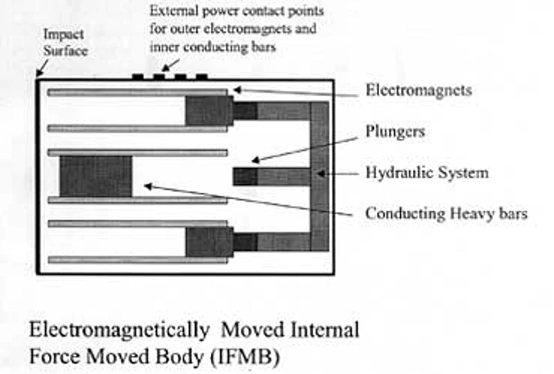
Figure 1. Elements of the electromagnetically Internal Force Moved Body
2.9 These two bodies collide with the wall at the other end, giving a further impetus to the forward motion of the entire container. This is half the cycle. The other half would involve the two bodies accelerating back, colliding with their corresponding plungers, and forcing the central inner body back against the wall from where it began the cycle. This process would further increase the velocity of the container.
2.10 In the cycle described earlier, at first the acceleration to the whole system would come from the forces required to move the masses backwards. While this would be partly negated by the drag forces, involved, the hydraulic system would make the oppositely directed kinetic energies involved be channeled such that they eventually gives an incremental velocity to the entire system, instead of dissipation as heat.
Advertisement
2.11 Thus after one cycle, the velocity becomes v, from rest or zero velocity. After another cycle, the velocity becomes 2v, then 3v, 4v, and so on. After n cycles the velocity of the container becomes nv.
2.12 There can be no upper limit to the velocity that can be reached by this system, in outer space, since there is no drag in outer space. On the earth, drag forces (air or surface resistance) will restrict the maximum speed. We now consider, mathematically, the implications arising out of the above discussions.
2.13 Consider such a closed container as described earlier in outer space. Let a cycle as described above increase the speed of the container by v. The internal energy required for doing that, let us say, is E. The total mass of the container is, say, m. The kinetic energy gained by the body as a result of the first hit is 0.5*m*v2, following the well-known formula. We should expect E to be rather greater than 0.5*m*v2 , as internal losses are involved. So let:
Advertisement
2.14 E = k * 0.5*m*v2
where k is a factor greater than one.
2.15 In outer space, there are no forces to retard the motion of the body. We assume that after another hit of same intensity, the velocity of the body increases by v with respect to its moving reference, and 2v with respect to its rest state.
2.16 (This is a major assumption, about velocity addition through internal force. It is justified by our current understanding of physics. However, so far this has not been proven by experiment. To prove this is the first task of anyone attempting to make a perpetual motion machine.)
Advertisement
2.17 After attaining the velocity v from the first (internal) hit, the body is at rest with respect to the inertial reference frame moving at v elocity v with respect to the earlier (zero velocity) reference. A second hit will increase this velocity by v with respect to that inertial reference frame moving at velocity v, or 2v with respect to the rest state.
2.18 After N hits, the velocity will be N*v. The kinetic energy of the body will be
0.5*m*(N*v)2,
2.19 while the total input energy required to bring it to that state will be
0.5*N*k*m*v2, as a result of N continuous hits.
Advertisement
2.20 The difference in input and output energy will be
0.5*N*m*v2*(k - N).
2.21 Now N can be unlimited, as we may have as many hits as required or mechanically possible. Whereas k is finite. So there is a negative energy output, which means that more energy is being created in this setup than lost. Which means the energy is being created by this particular engineering method, out of nothing. So, the law of conservation of energy is not correct, where bodies driven by internally generated forces are concerned.
2.22 We now give further details about the Electromagnetically Moved Internal Force Moved Body, shown in Figure 1.
Advertisement
2.23 The three inner masses (the central and the two outer) are heavy bars, composed of iron with many partitioning insulations for large parallel currents. They rest on non-magnetic surfaces, and can carry a great deal of current. The direction of the current is perpendicular to the magnetic field created by electromagnets that sit on the top and bottom sides of the heavy bar. The result will be that this bar will be subjected to a large force, which will accelerate it causing it to hit the central plunger of the hydraulic system. The equal and opposite force, acting upon the electromagnet assembly fixed to the container, will make the container accelerate in the opposite direction up to the moment of impact.
Advertisement
2.24 When the bar hits the plunger, it compresses and so acts upon the hydraulic system instead of dissipating heat as a result of the collision. The two outer arms of the E-shaped hydraulic system, as a result of the extra fluid suddenly squeezed into them, will fling forward two masses similar to the heavy bar discussed. (That is, these masses corresponding to the outer arms are also composed of iron with many partitioning insulations for large parallel currents, and they too can be pushed back by electromagnets). These masses will hit the inner wall at the other end, and thus impart their momentum to increase the velocity of the container. After that impact, the electromagnets will accelerate the outer bars back hard on to the corresponding outer plungers of the hydraulic system. This will push back the central bar, which will hit the same inner wall hit in the first half of the cycle by the outer bars. The velocity will be further increased. One complete cycle is now completed. In the next cycle the velocity will be increased by the same amount, with the same input application of internal energy required to power the electromagnets and the currents in the bars.
Advertisement
2.25 The above gives the rough idea for the design. It is cheap, reliable and energy-efficient. The main material involved is iron, so plentifully available. The fluid in the hydraulic system should have high cohesion.
2.26 An example: Assuming 50% losses (k=2), a 1000 watt energy input would increase the velocity of a 10 kilogram container by 10 meters per second every second. In one minute, the body would reach the speed of 600 meters per second. It would then have a kinetic energy of 180,000 joules, with respect to the inertial reference. However, only 60,000 joules of energy would have been expended. The unaccounted for 120,000 joules is energy obtained from nothing. It is up to us to exercise engineering ingenuity to tap this energy, obtained without use of nuclear, solar, geo-thermal, tidal, hydro-electric or fossil source.
Advertisement
2.27 For the purpose of demonstration of the principle of "velocity addition", a battery attached to the container could be used to provide the currents in the bars, and also the electromagnetic field. Naturally, this battery will run out fast, but not before it accelerates the mass very fast to provide a convincing demonstration.
2.28 When this container is powered by a source of electricity that never runs out of power (the designs for such an undying battery will be given in the following paragraphs 3.0 to 3.16) we shall have a self-powered vehicle, for terrestrial and extra-terrestrial travel.
3.0 Exploratory Engineering designs of Perpetual Motion Machines.
Advertisement
3.1 Designing an engine that delivers more power than it takes to run has been the top desire for all engineers. Many attempts have been made, especially in the field of electric motors. Always, they have failed. One such means was to use magnets to pull an iron mass up an incline, make it fall through a hole at the top, and use the kinetic energy gained to generate power, in a cycle. The following designs are the only ones based upon the bold assertions of the fallibility of Newton's First Law of Motion, and in the resulting mathematically proven disbelief for the Law of Conservation of Energy. They are backed by the mathematically derived predictions shown.
Advertisement
3.2 First, a simple, direct, linear design, which while showing the basic principles, is not really practical:
3.3 Imagine a single very heavy Internal Force Moved Body (IFMB) on a very smooth surface (such as ice, or rolling on ball-bearings). It accelerates from one end, and hits at high speed a bar (suitably padded to minimise noise pollution!) attached to a system of very powerful springs. The kinetic energy of the IFMB is transferred to the potential energy in the springs. Left just to themselves, they would push the IFMB back with equal speed. Some clever engineering could involve their transferring such potential energy to push back something else: such as a bar that is attached to a gear turning an enormous flywheel. The rotational energy of this flywheel is turned to electrical energy using a standard generator. If the mathematics involved in "velocity addition", leading to the violation of the law of conservation of energy, is justified, more energy will be generated than consumed.
Advertisement
3.4 Part of the electrical energy generated by this generator is used to drive the IFMB. Initially, some battery, on some other device should drive it. The electrical energy generated should charge the battery.
3.5 After the IFMB stops at the other end, it is made to accelerate in the other direction. For the IFMB driven by electro-magnetic fields, this means change in direction for the current flowing through the bar. There is an identical situation at the other end - the IFMB once again hits the system of springs which convert the kinetic energy to electrical energy. The IFMB keeps on moving backwards and forwards on the smooth bed, connected to the generator all the time.
Advertisement

Figure 2. Linear Design for Perpetual Motion Machine
3.6 The above design is easy to visualise. Let us see how much energy is generated, after putting in some realistic input values.
3.7 Let the IFMB weigh 2000 Kgs, and reach a speed of 150 Km/hour at impact. Then the kinetic energy will be, at impact, around 1.7 million joules. If we lose 0.7 million joules because of inefficiencies and the drive for the IFMB, we have 1 M joule. If this time for a hit takes 5 seconds, we have a fairly respectable 200 KWatt power plant using just one such IFMB. (For comparison, experimental nuclear reactors generated similar levels of power output, but very large power plants generate about a thousand times more power.)
Advertisement

Figure 3: Side View of Internal Force Engine
3.8 A better, and more practical, design, which is also rather more complex and presents many engineering challenges, is now presented. It is also portable. Theoretically at least it is scalable in size. It could power any existing moving vehicle.

Figure 4. Top view of Internal Force Engine.
3.9 Imagine a hollow airless ellipsoidal container. Along its axis is a hollow shaft, which can rotate with minimum friction upon bearings. The general idea is to rotate this shaft to a very high speed using IFMBs, thereby increasing the rotational kinetic energy for the shaft. This power is converted into electrical energy; the shaft is also the armature for an electricity generator. As power is drained off, the shaft loses its angular speed; when this speed drops to a certain level the IFMBs start moving fast once again, then stop when the high speed is attained. So the current to the IFMBs is not continuously applied.
Advertisement
3.10 The IFMBs are connected at the outer end of hollow spokes joined to the shaft. There may be many of them, but care should be taken to ensure that the whole system remains balanced. Electricity to power the IFMBs is directed from the external batteries through the hollow shaft and the spokes. Extra weights, to increase the moment of inertia, and for perfect balancing, are also attached to the shaft by such spokes.
3.11 For balance or redundancy, there should be two generators, one at the top and one at the bottom. A battery is used to start the IFMBs, but once they have started up, electricity is generated, and a feedback loop ensures that overall external power is not needed, while the battery is always kept fully charged.
Advertisement
3.12 The above design should be reliable - for routine maintainance only the bearings need to be checked. Faulty IFMBs could be replaced on a modular basis.
3.13 The IFMBs can move at very high speed, limited by the air resistance and friction at the bearings. However, the problem of centrifugal force does exist - it will affect the moving parts within the IFMB, by trying to throw them away. Overcoming the effects of centrifugal force should be one of the key challenges.
3.14 Some calculations, now. Since the IFMBs can move very fast, let us say that they reach a very high angular speed, say 500 rotations per second.


